Fusion 360 Sheet Metal Unfold Drawing

Video Tip Fusion 360 Sheet Metal Flat Pattern And Unfold Youtube

Sheet Metal Body Will Not Unfold Can Anyone Tell Me Why Autodesk Community Fusion 360
How To Export A Dxf Of A Sheet Metal Component In Fusion 360 Fusion 360 Autodesk Knowledge Network

Can T Make Drawing With Folded And Unfolded Version Of Sheet Metal Autodesk Community Fusion 360
Https Encrypted Tbn0 Gstatic Com Images Q Tbn 3aand9gcs9zmawyas0zzztlob3jmpj7fsqwbkbpwrdlg Usqp Cau
Autodesk 360 Sheet Metal Flat Pattern On Curved Surfaces Youtube

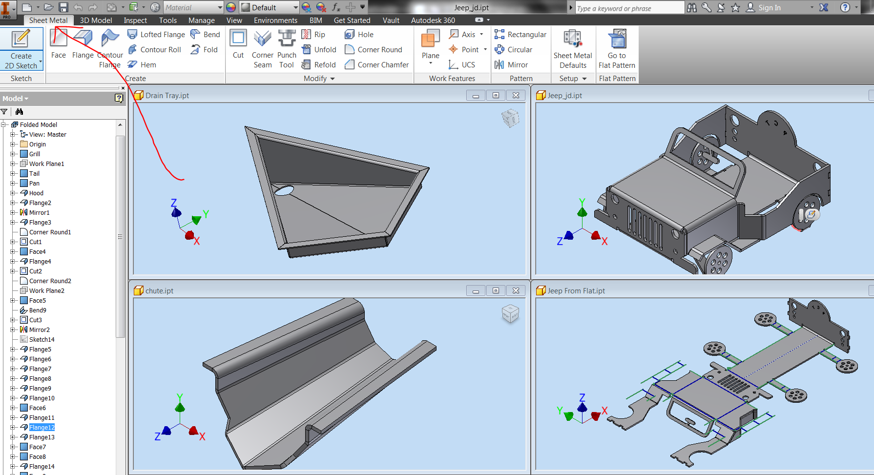
This integration ensures a design change made anywhere in the process from concept to production will reflect everywhere.
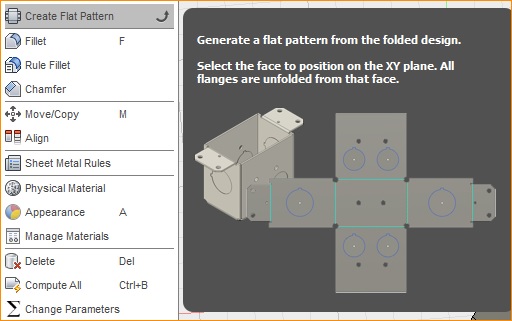
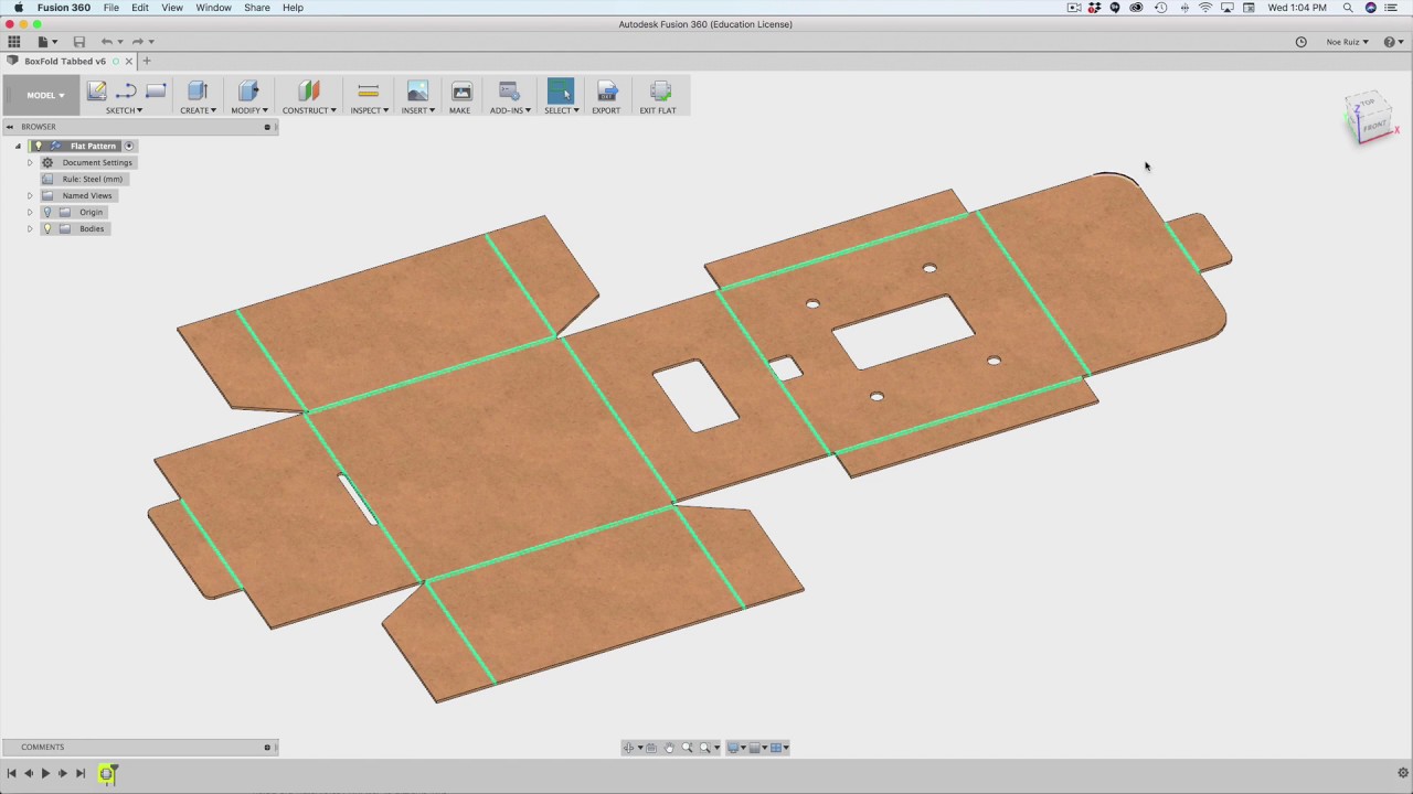
Fusion 360 sheet metal unfold drawing.

Step By Step Unfolding Sheet Metal In Drawing View Autodesk Community
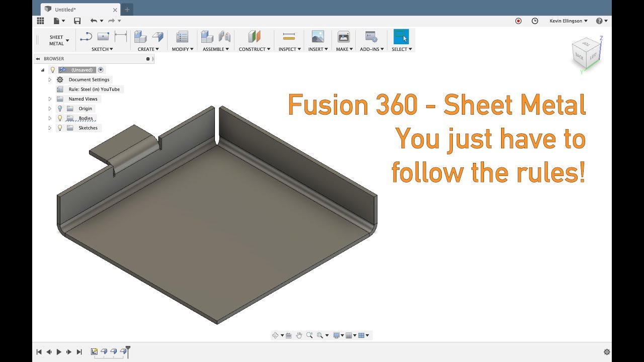
Fusion 360 Tutorial Foldable Boxes Youtube
Sheet Metal Design Autodesk Community Autocad

Design Sheet Metal Parts In Fusion 360 Toglefritz S Lair

Solved How To Make A Cone In Sheet Metal For Unrolling Autodesk Community Fusion 360

Unfold Circular Components Fusion 360 Sheetmetal Tutorial Youtube

Inventor Sheet Metal Drawings Youtube
Fusion 360 Flat Pattern Hole On Cylindrical Face Youtube

Sheet Metal Flat Patterns Search Autodesk Knowledge Network
Https D1ozhi4p59900 Cloudfront Net Files Urn Adsk Content Library 78756fcf E6f3 4184 Abdd 04afc0337a02 Classhandoutmfg225530sheetmetallikeaprowithfusion360robertsavage Pdf Expires 1609459199 Signature Dbexzkreykgvg Pbvjgrnj3gikkghyfnuolx2gunye Ugz7w2jw7rqxoeiyfibixywrsimdkfyntux51tdxlmmvfg3cksxtob1cqx9hyp37 Dpdf5egb Oe97szbiezko8t1zm6rqgun1ycetg 3d8f27k3jcetam61ejyznymymx0gsr Ao64p1suybv1ed50wu3hevbifcwicvlks4g1eyx4k4sjrowicn2towuuylfiw8wjnmfbn153wqq8zjrxzih4ntgbbthicfcunip5ljdsyf5 Dek4qil9lkwhka2mqflbxuxu3 8cza294kkliu5facj Nsm54dzjuluw Key Pair Id Apkaia22nyyfu6jzr5za

Fusion 360 Sheetmetal Upgrades Micrographics
Fusion 360 Unfolding Sheet Metal Tubing Youtube

Fusion 360 Sheet Metal How To Use Unfold Command Tutorial Youtube

Solved Sheet Metal Flat Pattern Drawing Autodesk Community Inventor

Advance Steel Folding And Unfolding Of Sheet Metal Part Youtube

Folding And Unfolding In Catia Sheet Metal Catia Practice Cad Designs Youtube

Pin On Nabm

Solidworks Tutorial Folding And Unfolding Sheet Metal Bends By Solidwize Solidworks Tutorial Solidworks Tutorial
3
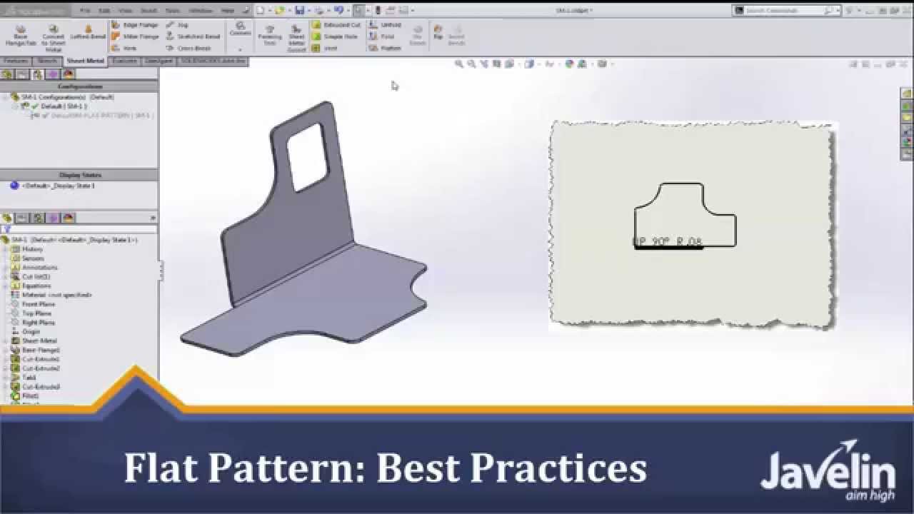
Solidworks Sheet Metal Tutorial Flat Pattern Best Practices Youtube

Control Panel Drawing Inventor 3d Sheet Metal For Fabrication Folded And Unfolded In Hindi Youtube

Precise 2 Unfold Sheet Metal Model In Autocad Sample 1 Youtube

Solidworks Sheet Metal 2d To 3d Sheet Metal Drawing Solidworks Tutorial Sheet Metal

Fusion 360 Ideastation Archived Autodesk Community
Source : pinterest.com
